没有合适的资源?快使用搜索试试~ 我知道了~
`1111111111111111111111111111111111111111111
资源推荐
资源详情
资源评论
1
INSTRUCTION MANUAL
DIN RAIL MOUNTING TYPE INDICATING CONTROLLER
DCL-33A
No.DCL31E3 2003.07
To prevent accidents arising from the misuse of this controller, please ensure the operator using it
receives this manual.
Caution
•
This instrument should be used according to the specifications described in this manual.
If it is not used according to the specifications, it may malfunction or breakdown.
•
Be sure to follow the warnings and cautions. Otherwise serious injury or accidents may occur.
•
The contents of this instruction manual are subject to change without notice.
•
Care has been taken to assure that the contents of this instruction manual are correct, but if there are
any doubts, mistakes or questions, please inform our sales department.
• This instrument is designed to be installed in a control panel. If not, measures must be taken to ensure
that the operator can not touch power terminals or other high voltage sections.
• Be sure to check that the power is turned off before cleaning this instrument.
• Use a soft and dry cloth when cleaning the instrument.
(If paint thinner is used, it might deform or tarnish the unit.)
• As the display section is vulnerable, do not strike or scratch it with a hard object.
• Any unauthorized transfer or copying of this document, in part or in whole, is prohibited.
• Shinko Technos CO., LTD. is not liable for any damages or secondary damages incurred as a result of
using this product, including any indirect damages.
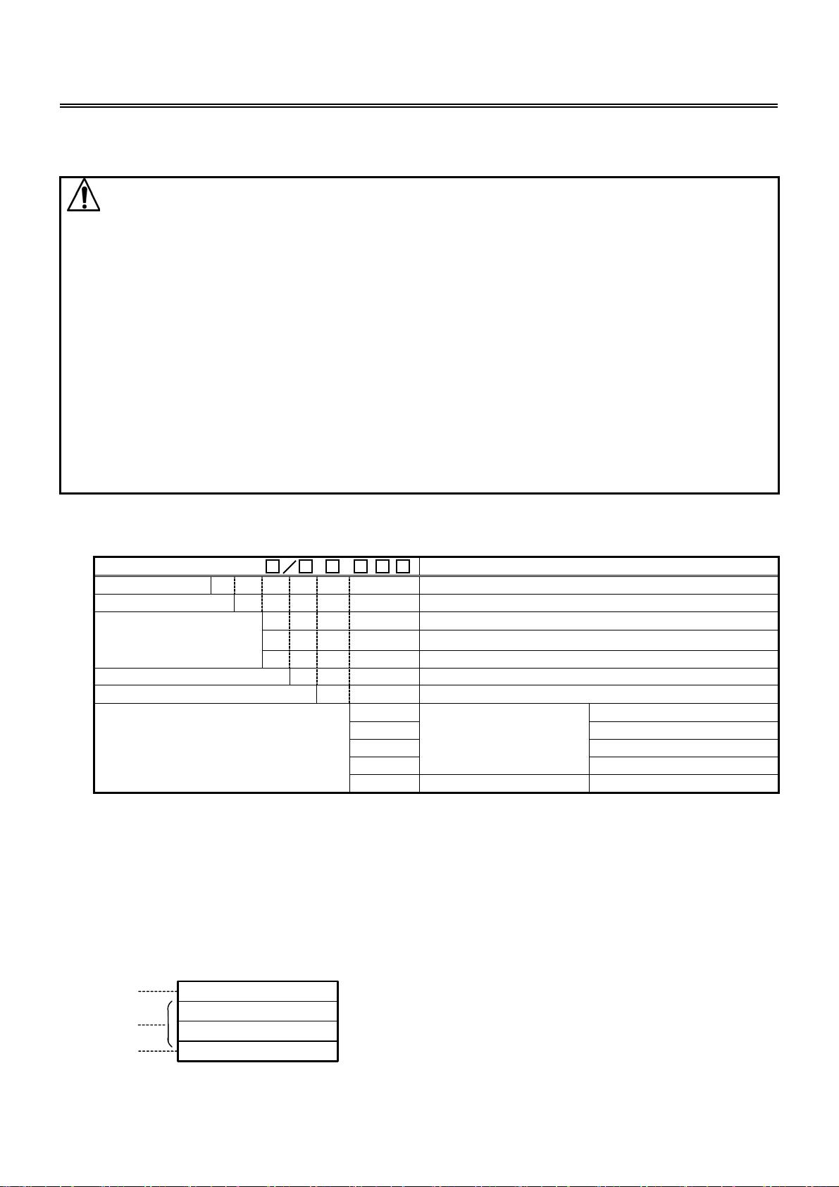
1. Model name
1.1 Model name
DCL - 3 3 A - , Series name: DCL-300 (W22.5 x H75 x D100mm)
Control action 3 PID
Alarm A Selectable by keypad operation *1
R Relay contact: 1a
S Non-contact voltage (for SSR): 12
+2
-0
V DC
OUT
(Control output)
A DC current: 4 to 20mA DC
Input M Multi-range *2
Supply voltage 1 Supply voltage 24V AC/DC *3
W (5A) CT rated current: 5A
W (10A) CT rated current: 10A
W (20A) CT rated current: 20A
W (50A)
Heater burnout alarm
CT rated current: 50A
Option
C5 Serial communication Based on EIA RS-485
*1: Alarm action (9 types and No alarm) and Energized/Deenergized can be selected by keypad operation.
*2: Thermocouple, RTD, DC current and DC voltage can be selected by keypad operation.
*3: Standard supply voltage is 100 to 240V AC. Write down “1” after the input code only when ordering
24V AC/DC.
1.2 How to read the model nameplate
Model nameplates are attached to the right side of the case and the inner assembly.
For Heater burnout alarm output, CT rated current value is written in the bracket ( ).
(1) Model name
(2) Option, supply voltage (Enter “1” only for 24V AC/DC)
(3) Instrument number (only on the inner assembly)
(1)
(2)
(3)
DCL-33A-R/M
W(20A)
No.XXXXXX
Model nameplate
(example)
Relay contact output/ Multi-range input
Heater burnout alarm output
2
2. Name and functions of the sections
(1) EVT indicator
A red LED lights up when Event output (Alarm, Loop break alarm
or the option Heater burnout alarm) is ON.
(2) OUT indicator
A green LED lights up when OUT (control output) is ON.
For DC current output type, this blinks in a 0.25 second cycle
corresponding to the output manipulated variable .
(3) T/R indicator
A yellow LED blinks during serial communication TX output
(transmission).
(4) AT indicator
A yellow LED blinks while PID auto-tuning is being performed.
(5) PV display
Indicates the input value (PV) with a Red LED.
(6) SV display
Indicates the setting value (SV) with a Green LED.
(7) Increase key (
)
Increases the numeric value.
(8) Decrease key (
)
Decreases the numeric value.
(9) Mode key (
)
Changes the setting mode or registers the setting value.
[Registers the setting value by pressing the Mode (
) key.]
(10) Sub-mode key
Brings up Auxiliary function setting mode 2 in combination with the mode key. (Fig. 2-1)
Caution
When setting the specifications and functions of this controller, connect the terminals 1 and 2 for power
source first, then set them referring to “5. Setup” before performing “3. Mounting to the control panel”
and “4. Wiring”.
3. Mounting to the control panel
3.1 Site selection
This instrument is intended to be used under the following environmental conditions (IEC61010-1):
Overvoltage category
, Pollution degree 2
Mount the controller in a place with:
•
A minimum of dust, and an absence of corrosive gases
•
No flammable, explosive gasses
•
Few mechanical vibrations or shocks
•
No exposure to direct sunlight, an ambient temperature of 0 to 50 (32 to 122 ) without rapid change
•
An ambient non-condensing humidity of 35 to 85%RH
•
No large capacity electromagnetic switches or cables through which large current is flowing
•
No water, oil or chemicals or where the vapors of these substances can come into direct contact with
the controller
3.2 External dimensions
(Fig. 3.2-1)
97
100
4
DIN rail
22.5
75
(1)
(2)
(5)
(6)
(3)
(4)
(7)
(8)
(9)
(10)
3
3.3 CT (Current transformer) external dimensions
CTL-6S (for 20A) CTL-12-S36-10L1 (for 50A)
(Fig. 3.3-1)
3.4 Mounting to DIN rail
Caution
Mount the DIN rail horizontally.
When DIN rail is mounted vertically, be sure to use commercially available fastening plates at the
end of DCL-33A series. Mount the DCL-33A series to the DIN rail so that the DCL-33A series may
be fixed.
However, if the DIN rail is mounted horizontally in a position susceptible to vibration or shock,
the fastening plates must be used as well.
•
Recommended fastening plate
Omron corporation End plate PEP-M
IDEC corporation Fastening plate BNL6P, BNL8P
Matsushita electric works, LTD.
Fastening plate ATA4806
(1) Hook
1
of the DCL-33A on the upper side of the DIN rail. (Fig. 3.4-1)
(2) Making
1
part of the DCL-33A as a support, fit the lower part
2
of the DCL-33A
to the DIN rail.
DCL-33A will be completely fixed to DIN rail with a “Click” sound. (Fig.3.4-1)
(Fig. 3.4-1)
4. Wiring connection
Warning
Turn the power supplied to the instrument OFF before wiring or checking it.
Working or touching the terminal with the power switched ON may result in severe injury
or death due to Electric Shock.
1
2
4
Caution
• Do not leave wire chips into the DCL-33A when wiring, because they could cause fire, malfunction
and trouble.
• Insert the connecting cable into the designated connector securely. Not doing so could cause
malfunction due to imperfect contact.
• Connect the AC power to the designated terminal as is written in this instruction manual. Otherwise it
may burn and damage the DCL-33A.
• Tighten the terminal screw with the specified torque. Excessive force could damage the terminal screw
and deform the case.
• Use a thermocouple and compensating lead wire that corresponds to the sensor input specification of
this unit.
• Use the 3-wire RTD that corresponds to the sensor input specification of this unit.
• When using DC voltage and current inputs, be careful not to confuse the polarity when wiring.
• When using a 24V AC/DC for the power source, do not confuse the polarity when it is DC.
• Keep input wires (Thermocouple, RTD, etc.) away from power source and load wires when wiring.
• Do not apply a commercial power source to the sensor connected to the input terminal nor allow the
power source to come into contact with the sensor.
• To prevent the unit from harmful effects of the unexpected level noise, it is recommended
that a surge absorber be installed between the electromagnetic switch coils.
• This unit does not have built-in power switch, circuit breaker or fuse. Therfore it is necessary to install
them in the circuit near the external unit.
(Recommended fuse: Time-lag fuse, Rated voltage 250V AC, Rated current 2A)
When using ferrules, use the following recommended ferrules and crimping pliers made by Phoenix
Contact GMBH &CO.
•
Recommended ferrules and tightening torque
Terminal
number
Terminal
screw
Ferrules with
isolation sleeve
Conductor cross
sections
Tightening torque Crimping pliers
AI 0.25-8 YE 0.2 to 0.25mm
2
AI 0.34-8 TQ 0.25 to 0.34mm
2
AI 0.5-8 WH 0.34 to 0.5mm
2
AI 0.75-8 GY 0.5 to 0.75mm
2
AI 1.0-8 RD 0.75 to 1.0mm
2
1 to 4 M2.6
AI 1.5-8 BK 1.0 to 1.5mm
2
0.5 to 0.6N・m
AI 0.25-8 YE 0.2 to 0.25mm
2
AI 0.34-8 TQ 0.25 to 0.34mm
2
5 to 9 M2.0
AI 0.5-8 WH 0.34 to 0.5mm
2
0.22 to 0.25N
・
m
ZA3
CRIMPFOX UD6
•
Terminal arrangement
• MAIN OUTPUT: Control output
• EVENT OUTPUT: Outputs when Alarm,
Loop break alarm or Heater burnout
alarm (option) is activated.
• RS-485: Serial communication
• TC : Thermocouple
• RTD : Resistance temperature detector
• DC : DC current or DC voltage
(Fig. 4-1)
Lower part of main body
CT input W
Communication
C5 (RS-485)
剩余19页未读,继续阅读
资源评论
wang4wang123
- 粉丝: 0
- 资源: 1
上传资源 快速赚钱
- 我的内容管理 展开
- 我的资源 快来上传第一个资源
- 我的收益 登录查看自己的收益
- 我的积分 登录查看自己的积分
- 我的C币 登录后查看C币余额
- 我的收藏
- 我的下载
- 下载帮助
安全验证
文档复制为VIP权益,开通VIP直接复制
信息提交成功