


SD Memory Card Sp
ecifications
PHYSICAL LAYER SPECIFICATION
Part 1
April 15 2001
SD Group
Matsushita Electric Industrial Co., Ltd. (MEI)
SanDisk Corporation
Toshiba Corporation
Version 1.01
(c)2000 (c)2001 by SD Group (MEI,SanDisk,Toshiba)
2
Date: April 2001
SD-Memory Card Specifications / Part 1. Physical Layer Specification; Version 1.01
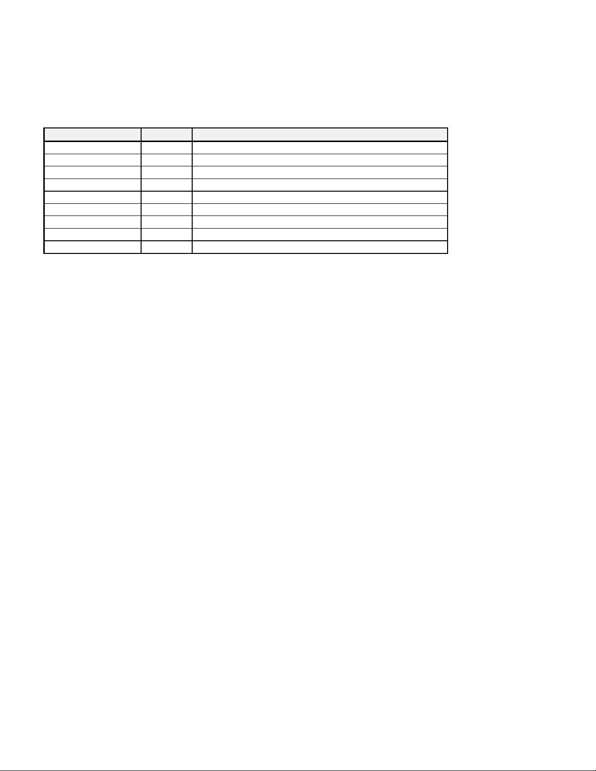
Revision History
Date Version Changes compared to previous issue
March 22th, 2000 1.0 Base version
April 15th, 2001 1.01
- The Supplementary Note (June 2000) that includes clarifications to
the spec was incorporated into the spec.
- Reliability/Durability - the open issues were defined (Torque/
Bending/WP Switch cycles)
- ESD: higher voltages for Non-contact/Air discharge were defined.
- Card’s Thickness tolerance were re-defined for the center area of
the card and more clarifications were added to the WP switch diagram
- Thin SD Card: Mechanical Drawing was added.
- More clarifications were added for SD Read Only Cards.
- Maximum time out for Write/Erase was changed to 250ms.
- Underrun/Overrun status bits were removed (non-relevant in SD
Card) from Table 22.
- Typo fixes and some clarification notes
- Update Fig 31 - Stop Tran during CRC response at Mult Blk WR.
- Add SD ROM Card type in SD_STATUS.
- Fix error in SEND_CID/CSD Ncr timing.
- A clarification about the operating frequency range were added (0-
25Mz mandatory for SD Card).
- Max Current during initialization period was re-defined.
- Initialization sequence in SPI mode for SD was updated.
Copyright (C)2000 (C)2001 by SD Group (MEI, SanDisk, Toshiba)
-
Exemption
:
-
Publisher and Copyright Holder:
None will be liable for any damage from use of this document.
Conditions for publication:
SD Group (MEI, SanDisk, Toshiba)

(c)2000 (c)2001 by SD Group (MEI,SanDisk,Toshiba)
3
Date: April 2001
SD-Memory Card Specifications / Part 1. Physical Layer Specification; Version 1.01
1 General description - 6
2 System features - 8
3 SD Memory Card System Concept - 9
3.1 Bus Topology - 9
3.1.1 SD bus - 10
3.1.2 SPI bus - 11
3.2 Bus Protocol - 12
3.2.1 SD bus - 12
3.2.2 SPI Bus - 15
3.3 SD Memory Card - Pins and Registers - 17
3.4 Compatibility to MultiMediaCard - 19
4 SD Memory Card Functional Description - 22
4.1 General - 22
4.2 Card Identification Mode - 23
4.2.1 Card Reset - 23
4.2.2 Operating Voltage Range Validation - 23
4.2.3 Card Identification Process - 25
4.3 Data Transfer Mode - 25
4.3.1 Wide Bus Selection/Deselection - 27
4.3.2 Data Read - 28
4.3.3 Data Write - 28
4.3.4 Erase - 29
4.3.5 Write Protect Management - 30
4.3.6 Card Lock/Unlock Operation (Optional) - 31
4.3.7 Copyright Protection - 33
4.3.8 Application specific commands - 34
4.4 Clock Control - 35
4.5 Cyclic redundancy codes (CRC) - 36
4.6 Error Conditions - 37
4.6.1 CRC and Illegal Command - 37
4.6.2 Read, Write and Erase Time-out Conditions - 37
4.7 Commands - 38
4.7.1 Command Types - 38
4.7.2 Command Format - 39
4.7.3 Command Classes (Redefined for SD Memory Card) - 39
4.7.4 Detailed Command Description - 40
4.8 Card State Transition Table - 45
4.9 Responses - 47
4.10 SD Memory Card Status - 49
4.10.1 Card Status - 49
4.10.2 SD Status - 52
4.11 Memory Array Partitioning - 53

(c)2000 (c)2001 by SD Group (MEI,SanDisk,Toshiba)
4
Date: April 2001
SD-Memory Card Specifications / Part 1. Physical Layer Specification; Version 1.01
4.12 Timings - 55
4.12.1 Command and Response - 55
4.12.2 Data Read - 56
4.12.3 Data Write - 57
4.12.4 Timing Values - 60
5 Card Registers - 61
5.1 OCR Register - 61
5.2 CID Register - 62
5.3 CSD Register - 63
5.4 RCA Register - 72
5.5 DSR Register (Optional) - 72
5.6 SCR Register - 72
6 SD Memory Card Hardware Interface - 74
6.1 Hot insertion and removal - 74
6.2 Card Detection (Insertion/Removal) - 75
6.3 Power protection (Insertion/Removal) - 75
6.4 Power up - 76
6.5 Programmable card output driver (Optional) - 78
6.6 Bus operating conditions - 80
6.7 Bus signal levels - 81
6.8 Bus timing - 82
6.9 Low Voltage (1.8v) SD Memory Cards (Preliminary) - 83
7 SPI Mode - 85
7.1 Introduction - 85
7.2 SPI Bus Protocol - 85
7.2.1 Mode Selection - 85
7.2.2 Bus Transfer Protection - 86
7.2.3 Data Read - 86
7.2.4 Data Write - 87
7.2.5 Erase & Write Protect Management - 89
7.2.6 Read CID/CSD Registers - 89
7.2.7 Reset Sequence - 89
7.2.8 Error Conditions - 90
7.2.9 Memory Array Partitioning - 90
7.2.10 Card Lock/unlock - 90
7.2.11 Application Specific commands - 90
7.2.12 Copyright Protection commands - 90
7.3 SPI Mode Transaction Packets - 90
7.3.1 Command Tokens - 90
7.3.2 Responses - 95
7.3.3 Data Tokens - 98
7.3.4 Data Error Token - 99
7.3.5 Clearing Status Bits - 99

(c)2000 (c)2001 by SD Group (MEI,SanDisk,Toshiba)
5
Date: April 2001
SD-Memory Card Specifications / Part 1. Physical Layer Specification; Version 1.01
7.4 Card Registers - 101
7.5 SPI Bus Timing Diagrams - 101
7.5.1 Command / Response - 102
7.5.2 Data read - 103
7.5.3 Data write - 103
7.5.4 Timing Values - 104
7.6 SPI Electrical Interface - 104
7.7 SPI Bus Operating Conditions - 105
7.8 Bus Timing - 105
8 SD Memory Card mechanical specification - 106
8.1 Card package - 106
8.1.1 External signal contacts (ESC) - 106
8.1.2 Design and format - 107
8.1.3 Reliability and durability - 107
8.1.4 Electrical Static Discharge (ESD) Requirements - 108
8.1.5 Quality assurance - 108
8.2 Mechanical form factor - 109
8.3 System: card and connector - 112
8.3.1 Card hot insertion - 112
8.3.2 Inverse insertion - 112
8.3.3 Card Orientation - 113
8.4 Thin (1.4mm) SD Memory Card (Preliminary) - 113
9 Appendix - 116
9.1 Power Supply Decoupling - 116
9.2 Connector - 116
9.2.1 General - 116
9.2.2 Card Insertion and Removal - 117
9.2.3 Characteristics - 118
10 Abbreviations and terms - 121


- 1
- 2
前往页